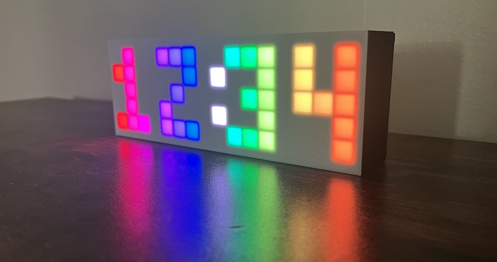
The Rainbow Clock is simply a digital clock with rainbow digits, but it’s also more than that: it is a tool for learning how to program LEDs. This website guides you through uploading your own code to the clock’s microcontroller to light up the grid of pixels with your own patterns.
The sidebar lists all the pages in this guide. If you want to understand more about how the clock is built, check out the pages in the “About the Rainbow Clock” section. If you’re ready to start coding, dive into Setup environment.
Long press the button for 2 seconds. Let go when the hours digit starts flashing.
Click the button to change the digit.
Long press the button for 2 seconds to move to the next digit. (The minutes digits are set separately.)
Click the button to change the digit.
Repeat for the last digit.
Long press the button again to return to the regular clock mode.
Unplug vs Turn off switch
If you unplug the clock, it will stop tracking time, but the time it was unplugged is stored and loaded next time you plug it in. So if you unplug it and replug 5 minutes later, it will be 5 minutes behind.
If you turn off the on/off switch, only the LEDs turn off, not the whole system. If you turn the switch off and leave the USB cable plugged in, the controller will still be powered, and it will still keep accurate time.
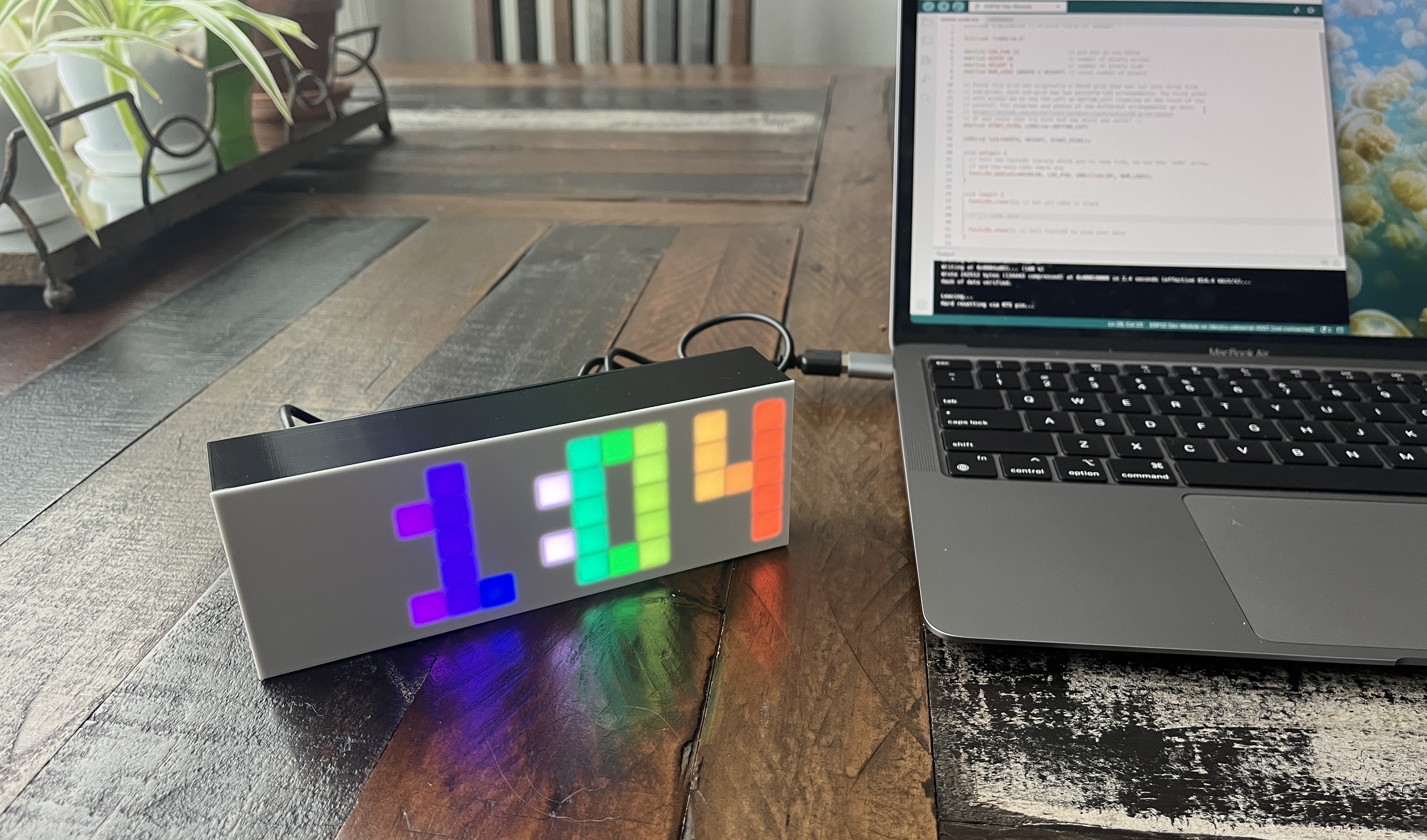
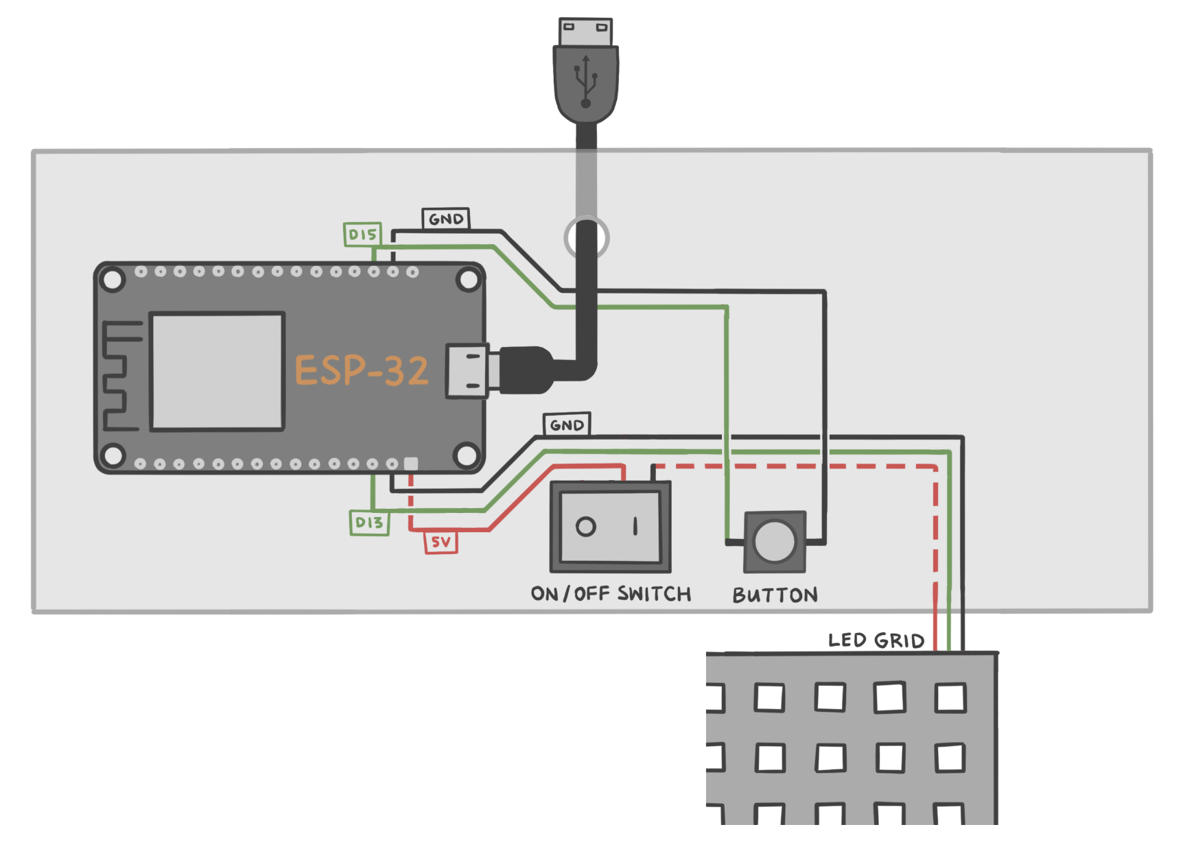
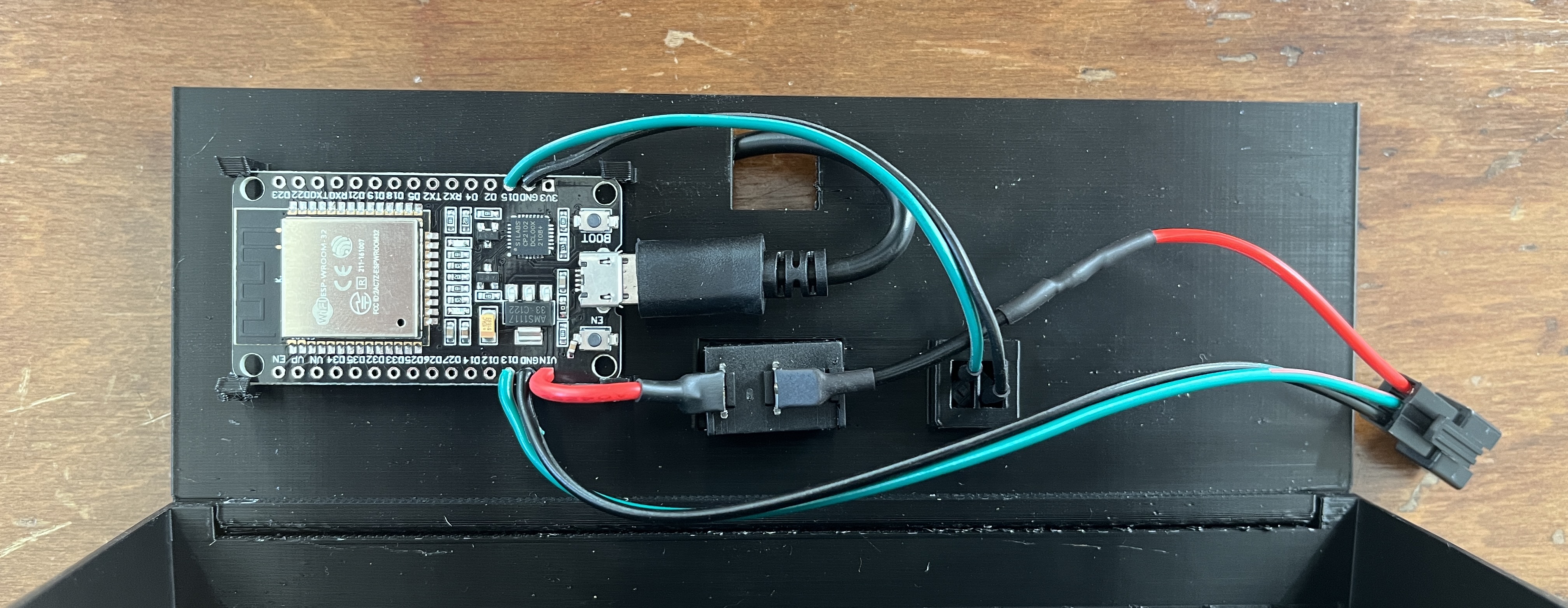
The clock itself is 3D printed, has an on/off switch on the back, and also has a button on the back for manually setting the time. The back panel of the clock hinges open to reveal a programmable ESP32 microcontroller and a 5x16 grid of LEDs. A data-sync capable microUSB cable is included.
The on/off switch only turns off power to the LEDs, not the whole system. So if you turn the switch off and leave the USB cable plugged in, the ESP32 board will still be powered, and it will still keep accurate time.
There are two different hardware configurations your clock could have. These two variations are accounted for in the code. This page explains these variations.
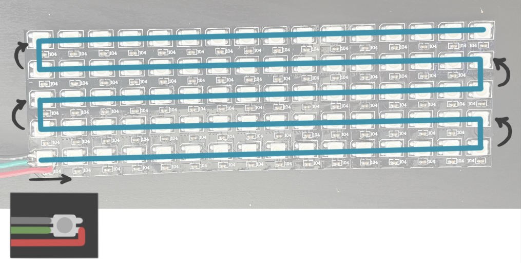
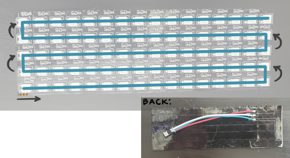
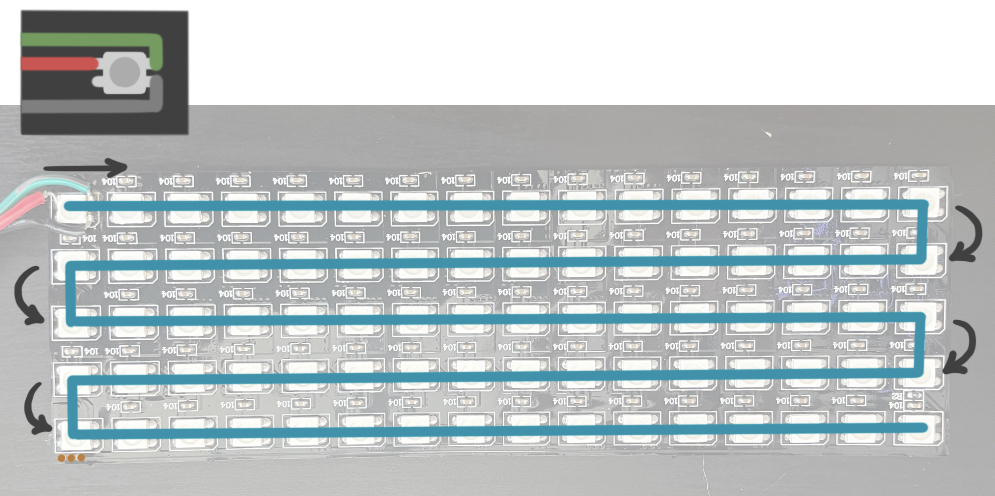
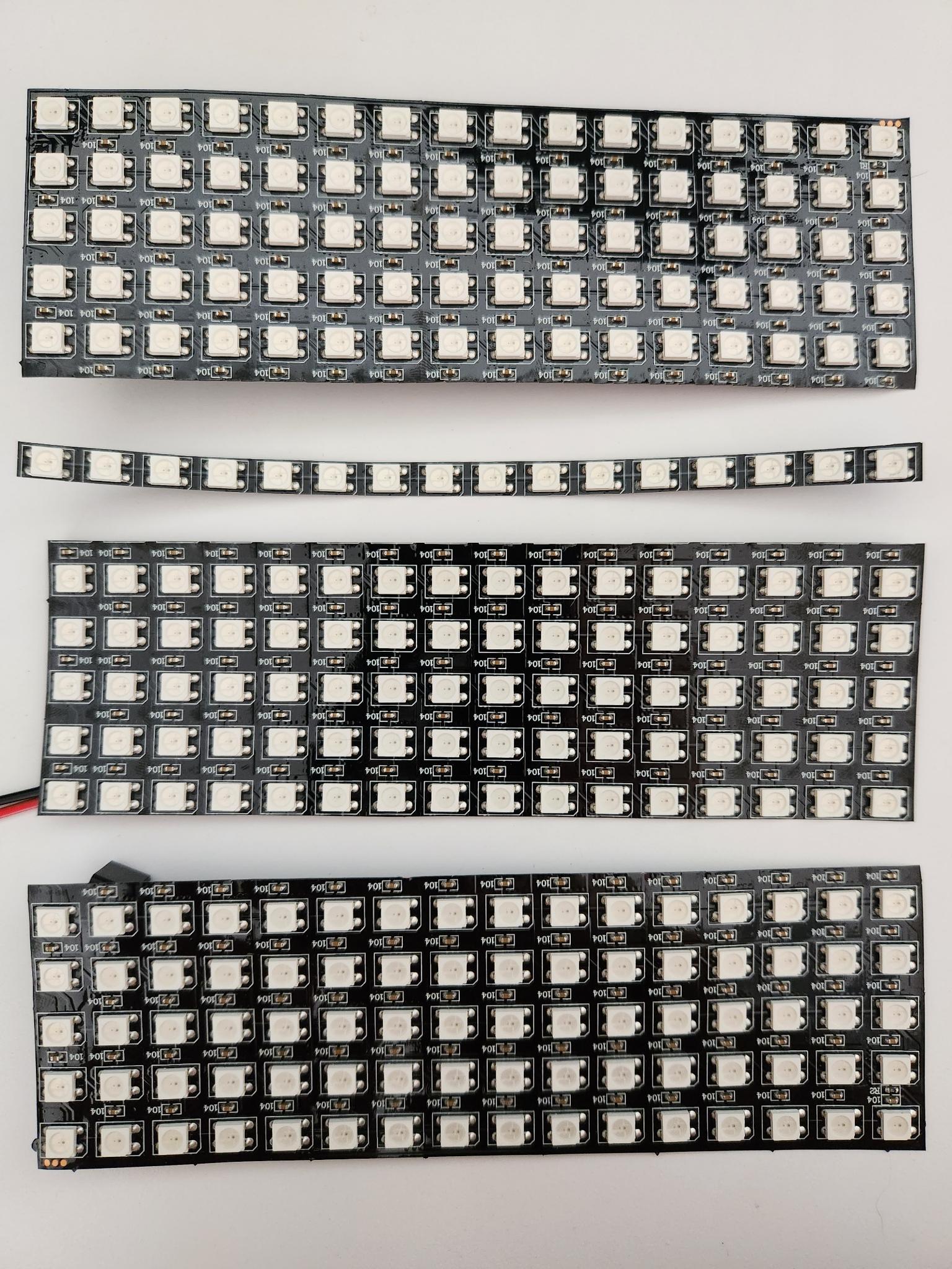
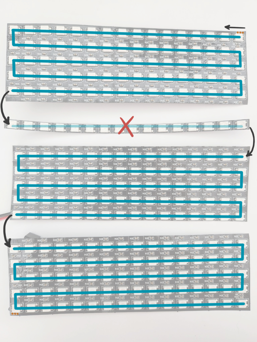
The 5x16 grid in the clock was originally a 16x16 pixel matrix that was cut into three 5x16 pixel sub-grids. Because the wiring embedded in these grids runs back and forth in a snake pattern, one of these three sub-grids has a different starting pixel position, and the arrangement of LEDs is flipped.
Your grid’s starting pixel should be on either the bottom left or the top left (looking at the front of the clock). You can hinge open the back panel of your clock to access your sub-grid. Then you can compare yours to the photos below to figure out which starting pixel you have.
If for some reason your starting pixel is on the right, rotate your grid 180 degrees so that it is on the left. The code only accounts for starting pixels on the bottom left or top left.
In the main file rainbow-clock.ino, there is a variable START_PIXEL. Change this variable to be set to LEDGrid::BOTTOM_LEFT or LEDGrid::TOP_LEFT according to your sub-grid’s start pixel.
#define START_PIXEL LEDGrid::BOTTOM_LEFT // or LEDGrid::TOP_LEFTLEDGrid leds(WIDTH, HEIGHT, START_PIXEL);
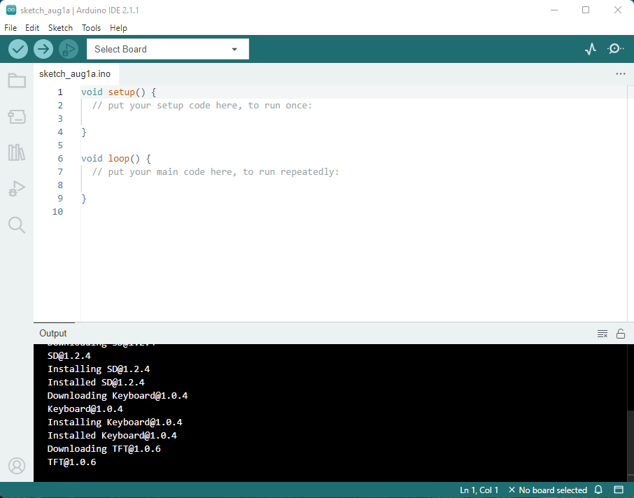
In order to upload your own LED code to the Rainbow Clock, you’ll need to install the Arduino IDE. This page will walk you through setting up the Arduino IDE to be ready to upload code to the rainbow clock.
There are two versions of the Arduino IDE: the newer Arduino IDE 2 and the Legacy IDE (1.8.X). Arduino IDE 2 is recommended but has specific operating system requirements, so the Legacy IDE is a good alternative for older systems.
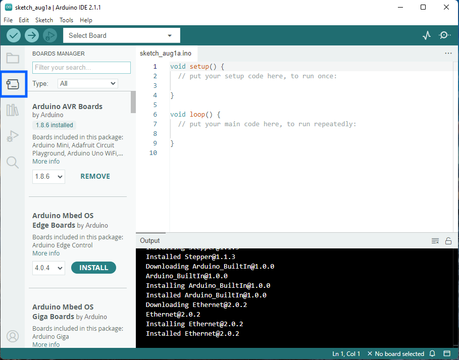
Now that you have the Arduino IDE, you’ll need to install the ESP32 board add-on within the IDE. (An ESP32 is a microprocessor just like an Arduino. The IDE comes ready to upload code to Arduino boards, but the ESP32 boards are special and need to be added separately.)
(Disclaimer: The steps and screenshots below are based directly on this guide: Installing ESP32 Board in Arduino IDE 2, with all screenshots freshly taken for this content.)
(If you have Legacy IDE 1.8.X, the steps are the exact same, but the screenshots won’t quite match. Here’s a guide specifically for Legacy IDE: Installing ESP32 Board in Legacy Arduino IDE 1)
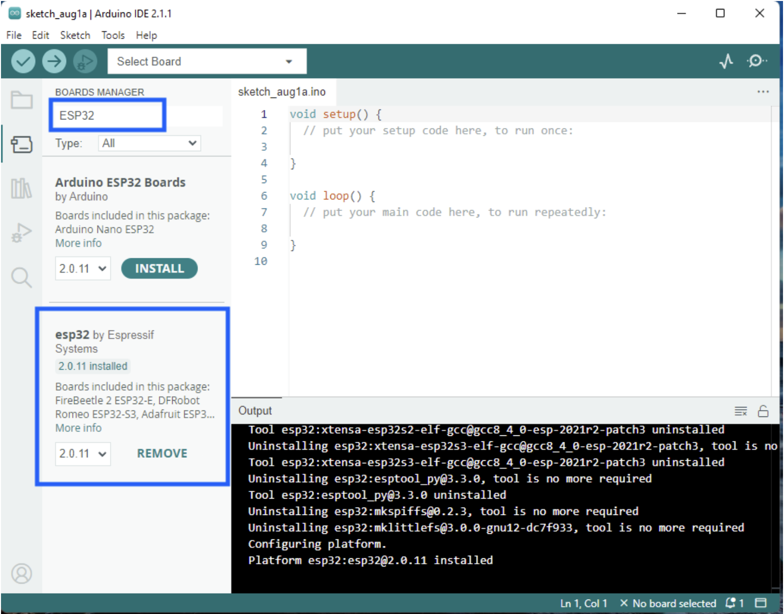
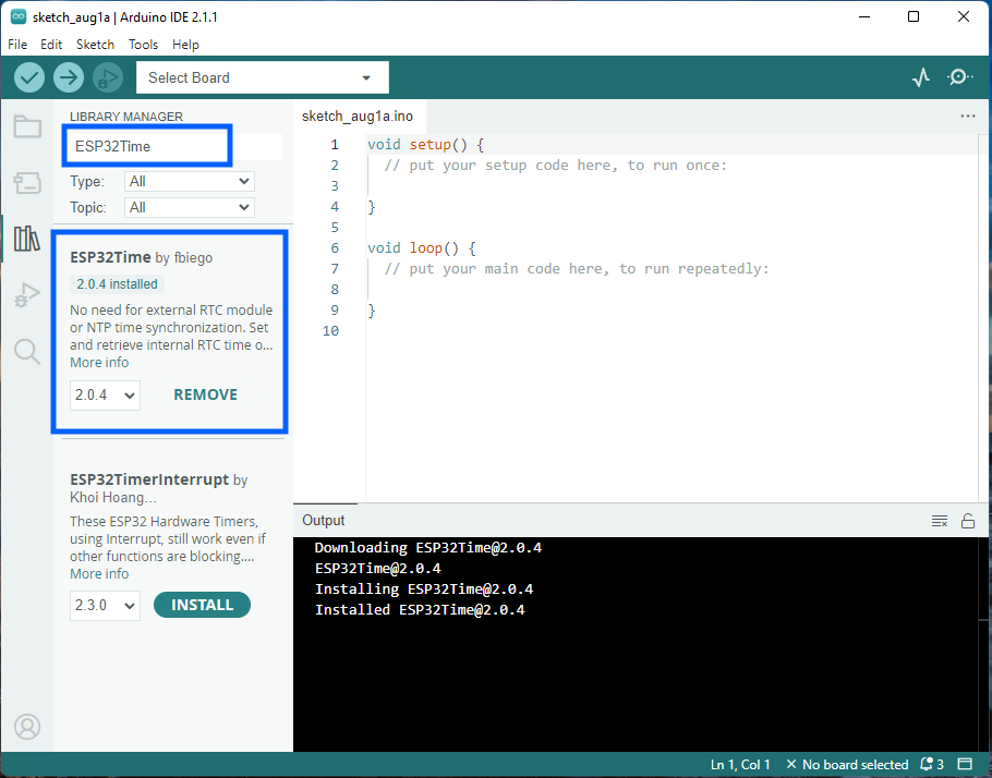
Type “ESP32” in the search field. Locate esp32 by Espressif Systems. Click Install. (This screenshot has a “Remove” button because it is already installed in this case.)
You now have the ESP32 board added!
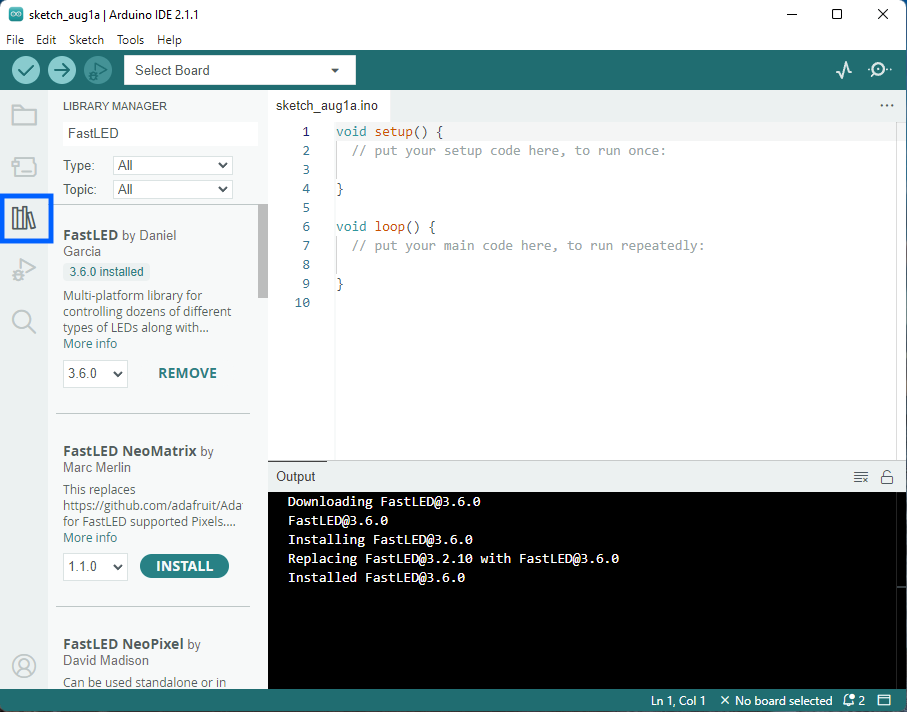
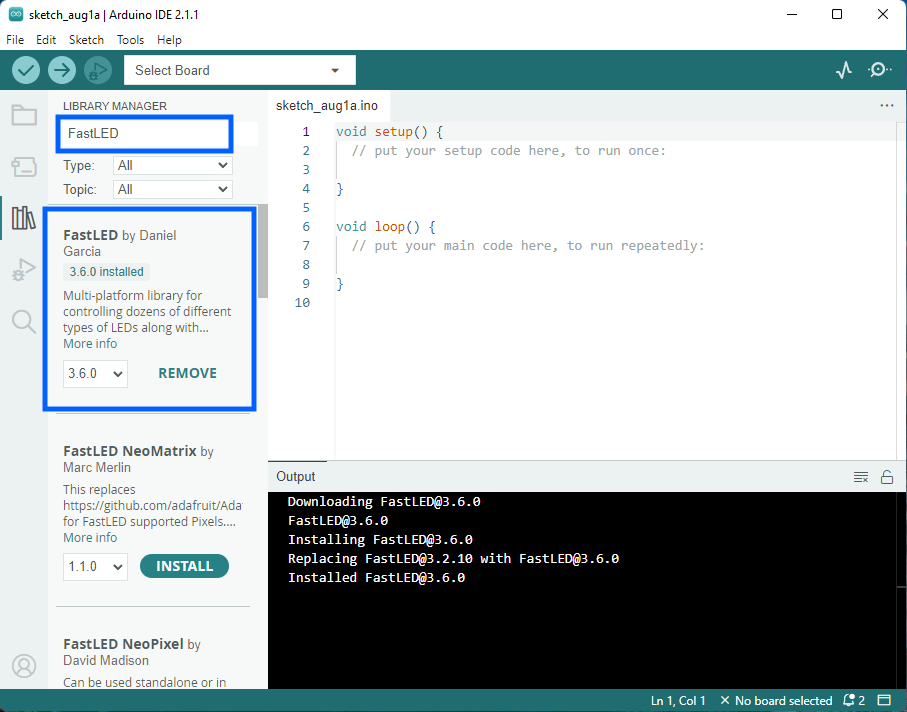
3. Install LED and Time libraries from the Arduino libraries manager §
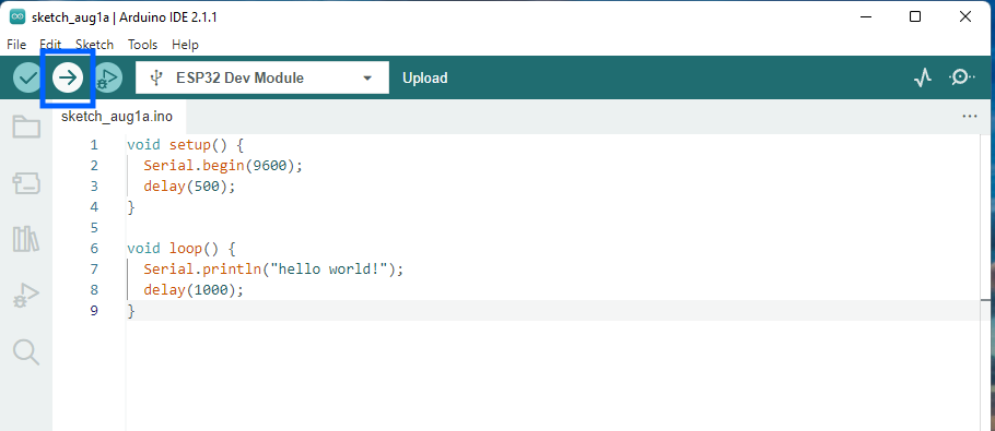
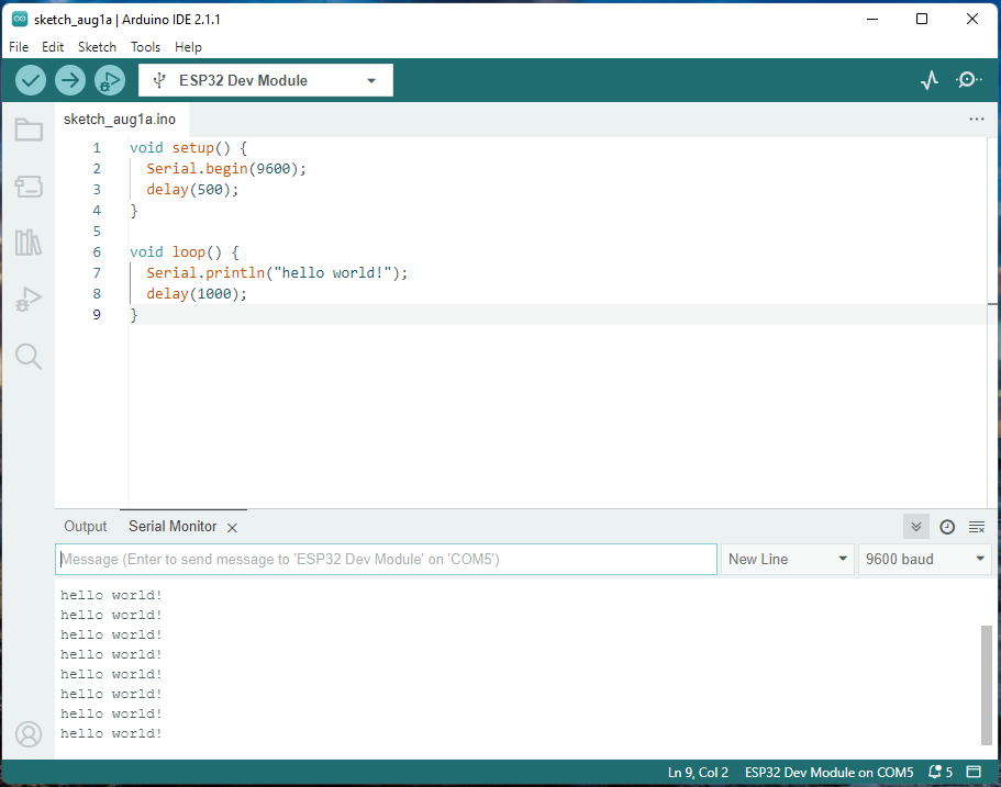
To make sure you have everything set up correctly, we’ll upload some test code to the Rainbow Clock’s ESP32 board. This test code prints the words “hello world!” every 1 second to the Serial monitor.
(Again, these steps and screenshots are copied from this guide, except with different test code.)
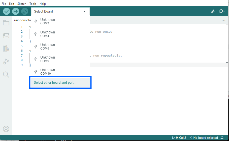
Make sure your Rainbow Clock is plugged into your computer. On the top drop-down menu, click the “Select Board” dropdown. Click Select other board and port…
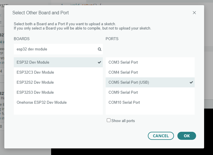
A new window will open:
Under “BOARDS” on the left, type “esp32 dev module” to filter, and then select ESP32 Dev Module.
Under “PORTS” on the right, select your board. It may have a different name other than COM, like /dev/cu.SLAB_USBtoUART, or /dev/cu.usbserial-0001. If you’re not sure which one to select, unplug the Rainbow Clock from your computer, then plug it back in, and see which option appears.
At this step, your computer might prompt you to download and install python3. You’ll need to allow it, as python is needed to upload to ESP32 boards. If you’re getting stuck on this step, this guide has more detailed steps regarding python.
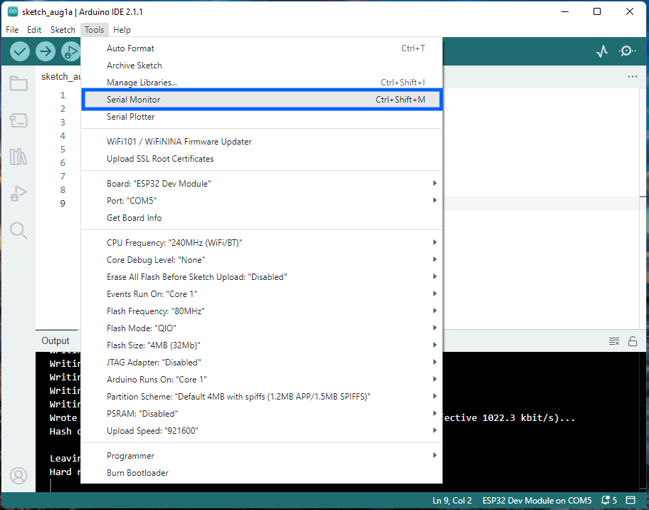
Verify that the code is running on the Rainbow Clock’s ESP32 by opening the Serial Monitor. Tools > Serial Monitor
The serial monitor shows up at the bottom below the code editor:
If you see “hello world!” printing every 1 second in your Serial monitor, it’s working! YOU DID IT! :) It might not be obvious, but this “hello world” code is running on your Rainbow Clock’s ESP32.
(If you see text but it’s random characters/jargon, make sure you select “9600 baud” on the right side of the serial monitor. 9600 should be the default.)
Now that you know how to upload code to the Rainbow Clock, you can start writing your more fun LED code!
This page will walk you through how to code some basic LED patterns, starting with turning on a single LED. Each pattern adds a layer of complexity onto the last, while calling out essential utility functions like map() and delay().
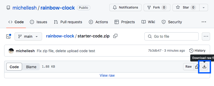
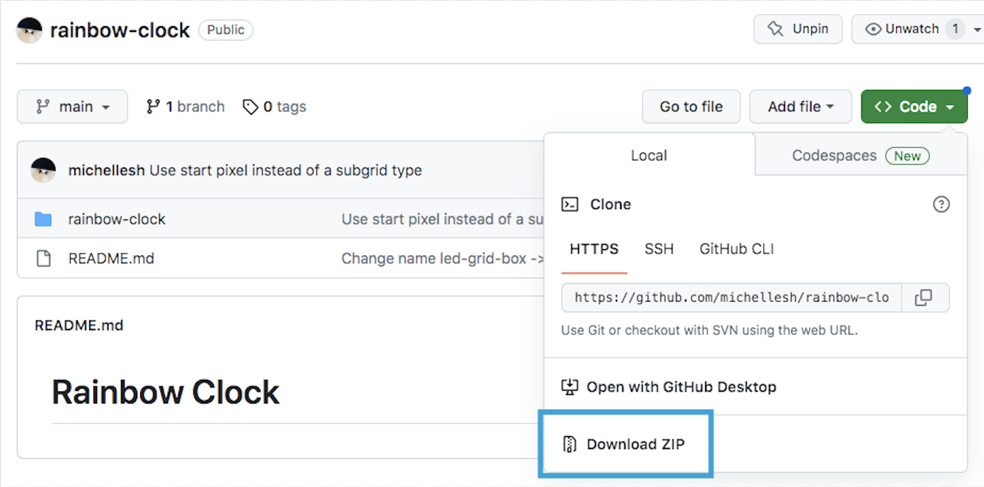
This will download a zip which contains two files. Once unzipped, open the folder. There should be two files in the folder: LEDGrid.h and starter-code.ino. Open the .ino file in the Arduino IDE.
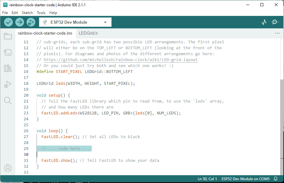
The rest of the examples on this page will assume that all of this surrounding starter code is present. When you paste code from each example below, paste below the comment: // ... code here ... (highlighted in the above screenshot)
Don’t delete any of the other surrounding code.
(You don’t have to understand all this surrounding code to start coding some LED patterns!)
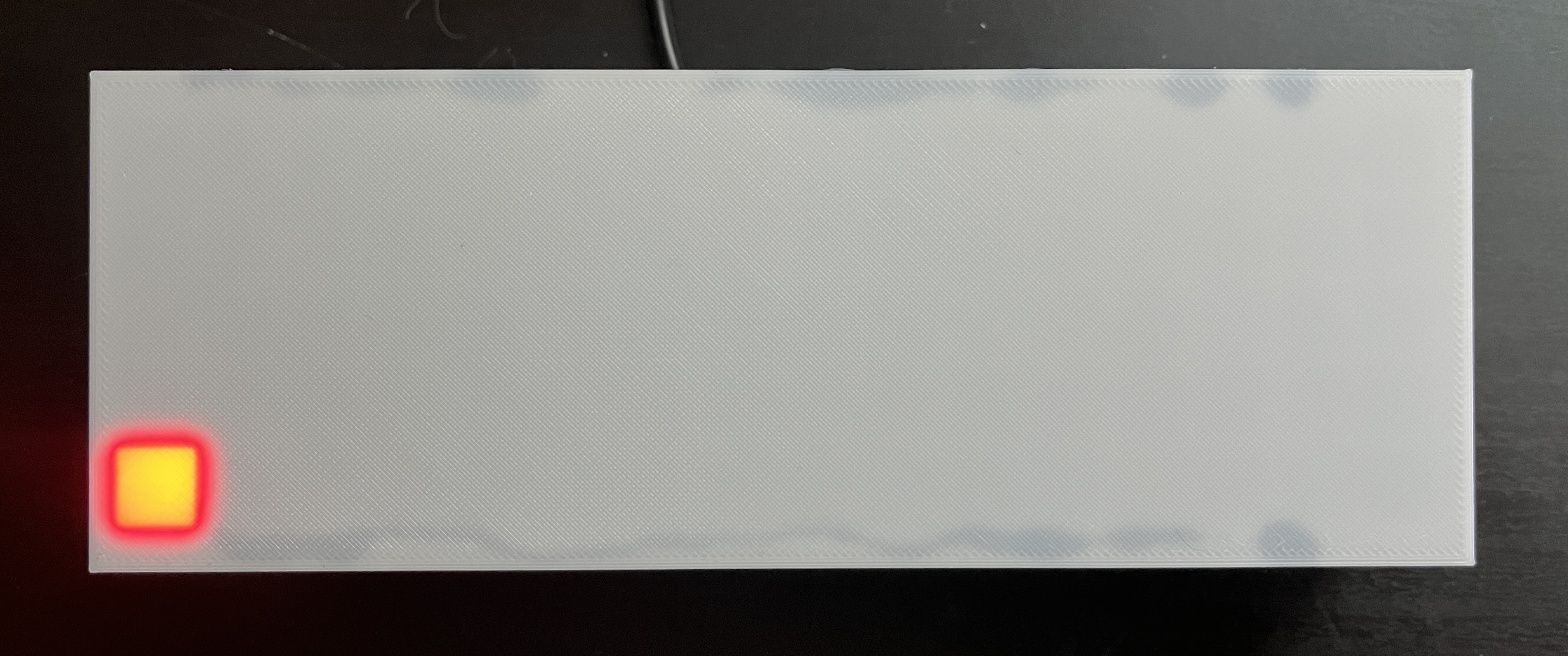
Paste the above code into the Arduino IDE editor where you see the comment // ... code here .... (It doesn’t matter if the tabs/spacing is messed up, but if you want it to look pretty, you can press ctrl-t on Windows or cmd-t on Mac to auto-format.) Then click the upload icon!
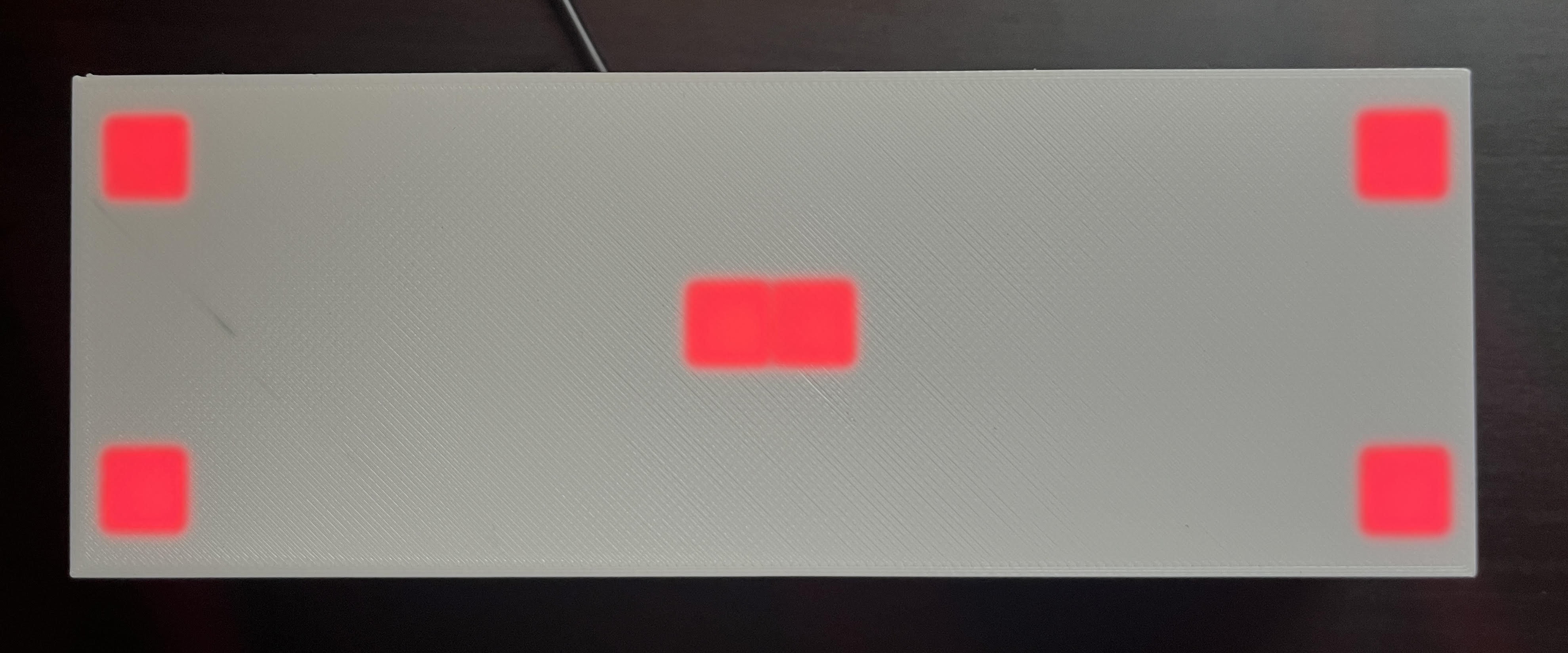
This code sets a single pixel at the (x, y) coordinate (0, 0) to Red. CRGB::Red is one of many pre-defined colors in the FastLED library. See the full list of FastLED predefined colors. Try changing CRGB::Red to CRGB::Blue or CRGB::Green!
NOTE
If the pixel that turned on is not at the bottom left, you probably need to change the START_PIXEL variable towards the top of the file.
#define START_PIXEL LEDGrid::TOP_LEFT // change to LEDGrid::BOTTOM_LEFT, or vice versa
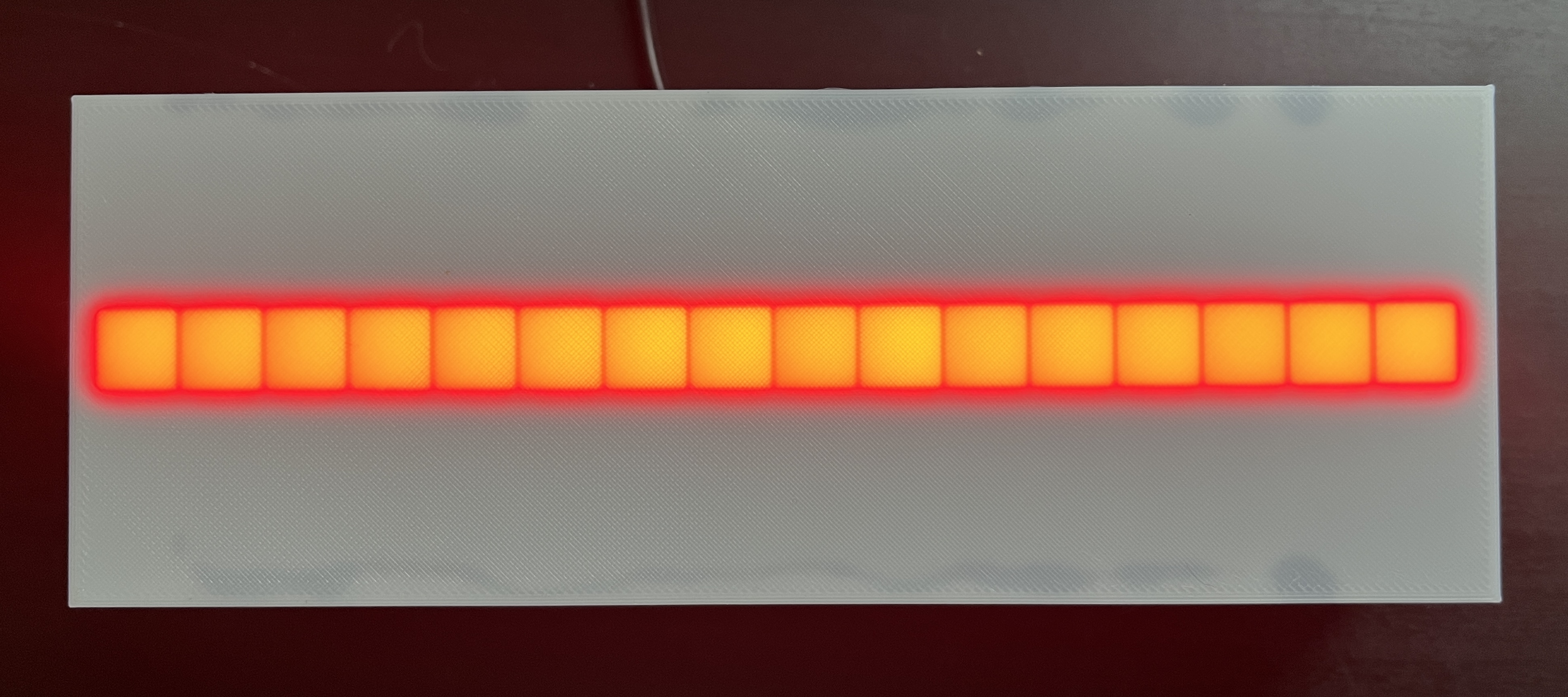
for (int x = 0; x < WIDTH; x++) { leds(x, 2) = CRGB::Red;}
This code loops through every value of x from 0 to WIDTH (which is 16) and sets the LED in row 2 at that x-coordinate to Red. (Detailed explanation of a for loop here.)
TIP
It doesn’t matter if the tabs/spacing gets messed up, but if you want it to look pretty, you can press ctrl-t on Windows or cmd-t on Mac to auto-format, or go to Edit > Auto Format.
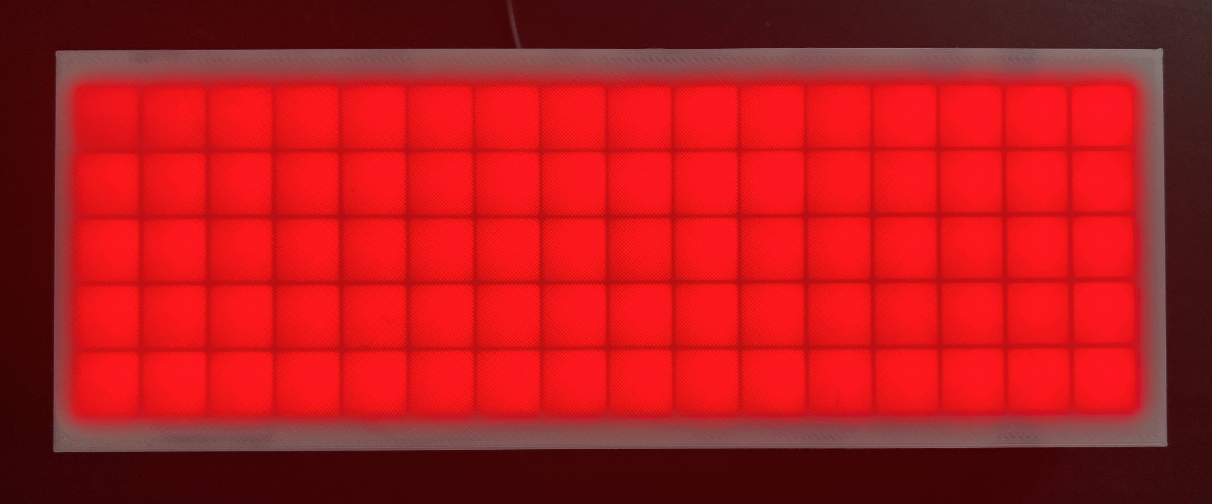
for (int x = 0; x < WIDTH; x++) { for (int y = 0; y < HEIGHT; y++) { leds(x, y) = CRGB::Red; }}
A doublefor loop! This one still loops through every value of x, and for each value of x, loop through every value of y from 0 to HEIGHT (which is 5). You can also think of x as column and y as row.
In addition to predefined colors like CRGB::Red, FastLED also allows you to set colors using two color models: RGB, and HSV (aka HSL). You can define these with the respective functions CRGB(red, green, blue) (CRGB documentation) and CHSV(hue, saturation, value) (CHSV documentation).
colorpicker.me is a useful and fun tool for understanding how colors are defined and for discovering new colors! Also keep in mind that not all colors map perfectly to LEDs. For instance you might find a nice light purple on colorpicker.me, try to send its RGB values to the LEDs, and get a boring dim white-ish color.
Here we define three variables red, green, and blue and set their values between 0-255. The following code sets all LEDs to the RGB color (9, 105, 218) (a rich blue color)
int red = 9;int green = 105;int blue = 218;for (int x = 0; x < WIDTH; x++) { for (int y = 0; y < HEIGHT; y++) { leds(x, y) = CRGB(red, green, blue); }}
hue, saturation, and value are all values between 0-255 in FastLED, but a typical HSV color has different ranges. Hue is usually a value 0-360 (as in 360 degrees on a color wheel), and saturation and value are usually percentages 0-100. To get the same blue color we got above as an RGB, we take the hue from colorpicker.me, which is 212 and we convert it from the 0-360 range to the 0-255 range: 212 * 255 / 360. Similarly we take the saturation and value 92% and 85% and convert them to the 0-255 range: 92 * 255 / 100 and 85 * 255 / 100.
int hue = 212 * 255 / 360;int saturation = 92 * 255 / 100;int value = 85 * 255 / 100;for (int x = 0; x < WIDTH; x++) { for (int y = 0; y < HEIGHT; y++) { leds(x, y) = CHSV(hue, saturation, value); }}
(Note that these RGB and HSV blues might be slightly different. The RGB <> HSV conversion is not perfect. You can see this for yourself in colorpicker.me if you try increasing or decreasing the “G” or “B” values by one, sometimes the HSV stays the same. So there could be multiple RGBs for a single HSV.)
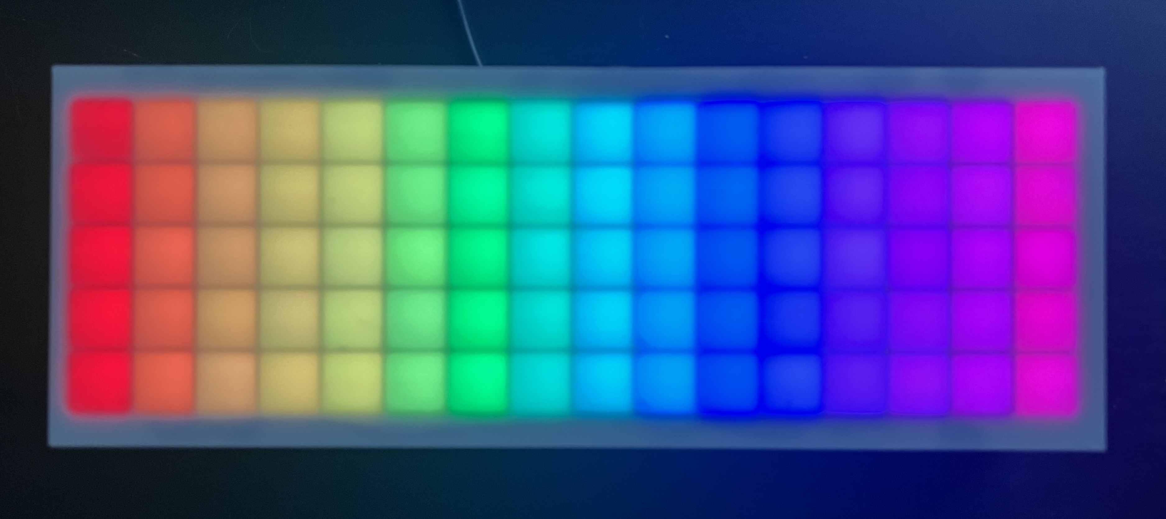
This one sets each pixel to a custom CHSV color instead of a pre-defined color like Red. The HSV color model takes the arguments (hue, saturation, value). saturation and value are both at their max of 255. We calculate the hue as a function of x. We do this with the map() function.
leds(0, 0) = CRGB::Red; // Set the pixel to RedFastLED.show(); // Tell FastLED to show your datadelay(1000); // Wait 1 second (1000 milliseconds)leds(0, 0) = CRGB::Black; // Turn the pixel offFastLED.show(); // Tell FastLED to show your datadelay(1000); // Wait 1 second (1000 milliseconds)
NOTE When you paste this into the starter code under // ...code here... , you’ll notice FastLED.show() gets called again after the pasted code. You can just leave that extra call in there. In this example, it doesn’t need to be called again after the last delay(1000), but it doesn’t hurt, and it’s easier to keep the same loop structure in place.
This code sets a single pixel to Red, tells FastLED to show that pixel, then uses the delay() function to pause for one second, then turns that LED to Black (off), show, pause.
int sinBeat = beatsin8(30, 0, 255); // 30 beats per minute, range 0-255for (int x = 0; x < WIDTH; x++) { for (int y = 0; y < HEIGHT; y++) { int hue = map(x, 0, WIDTH, 0, 255); // map the current x from 0-WIDTH to a hue in the range 0-255 leds(x, y) = CHSV(sinBeat + hue, 255, 255); // add a sine wave to hue to make it oscillate } }
This one creates a sine wave using beatsin8() to get a value that oscillates between a given range over “time” (ie. as the loop gets called over and over). It uses that sine wave to offset the hue, so that the hue at a given column is changing, creating the illusion that the whole picture is moving back and forth.
int sinBeat = beatsin8(30, 0, 255); // 30 beats per minute, range 0-255
The beatsin8 function is a FastLED beat generator which returns a sine wave in a specified Beats Per Minute, and with a specified low and high range for the output. The 8 stands for an 8-bit value, meaning the number can range from as low as 0 to as high as 255. The range of a hue is also 0-255 so we will utilize that whole range.
Let’s talk about why this sinBeat + hue part works.
The sinBeat variable we’ve already defined as a number oscillating in the range 0-255
The hue variable is calculated as a function of x and converted to a number in the range 0-255. So when x is 2, hue is 32 (red-ish-orange)
The sum sinBeat + hue is passed into the first argument of the CHSV function. According to the documentation, the hue variable is a type uint8_t - an 8-bit number from 0-255. (Unlike an int variable which can be anywhere in the range -2,147,483,648 to 2,147,483,647) So what happens if we pass in 256? It will wrap around to the beginning and turn into 0. This will always happen when you set any uint8_t variable to 256. Similarly 257 will be 1, 258 will be 2, etc.
Example: if we look at only the 3rd column of the grid, where x = 2, hue becomes 32 (red-ish-orange), then we add sinBeat which oscillates between 0-255, making the sum oscillate between 32-287, but 287 wraps around to 32. So the color at that columns is oscillating from red-ish-orange, to the end of the rainbow, wraps to the beginning, then to 32, then reverses all the way back.
I believe the best way to learn programming is to try changing the code, running it, and seeing what happens. Get curious about what would happen if you change this variable to that, move this line of code there, etc. And see what happens! Sometimes it looks terrible! Sometimes it turns out different than expected, and sometimes that even leads to a new idea. :) What designs can you create? What colors did you make up? What’s the RGB code for your favorite color? Can you make some animations?
I would LOVE to see your creations. Post them on Instagram and tag @mickymakes.art!
A few issues have been compiled on the Troubleshooting & FAQ page, which will be updated over time as feedback is collected on any additional issues users encounter.
If you’ve uploaded your own code to the Rainbow Clock and you want to go back to using it as a clock, this page will walk you through how to upload the original clock code: How to re-upload the original clock code
If you’ve uploaded your own code to the Rainbow Clock and you want to go back to its original function as a clock, this page will walk you through how to upload the original clock code.
Unzip and open the folder called rainbow-clock-main
Open the file rainbow-clock/rainbow-clock.ino in the Arduino IDE. If you don’t have the Arduino IDE installed, you’ll need to follow at least the first three steps on the Setup environment page to install the Arduino IDE, add the ESP32 board within the IDE, and install the libraries FastLED and ESP32Time.
Make sure you set the right START_PIXEL set according to if your grid’s starting pixel is on the bottom left or top left. You can open your clock to check this, or you can just try one and see if the numbers are displayed upside down!
In the file rainbow-clock/rainbow-clock.ino:
#define START_PIXEL LEDGrid::TOP_LEFT // or LEDGrid::BOTTOM_LEFT
Connect the Arduino IDE to your clock’s ESP32. Make sure your Rainbow Clock is plugged into your computer. On the top drop-down menu, click the “Select Board” dropdown. Click Select other board and port…
A new window will open:
Under “BOARDS” on the left, type “esp32 dev module” to filter, and then select ESP32 Dev Module.
Under “PORTS” on the right, select your board. It may have a different name other than COM, like /dev/cu.SLAB_USBtoUART, or /dev/cu.usbserial-0001. If you’re not sure which one to select, unplug the Rainbow Clock from your computer, then plug it back in, and see which option appears.
Click “OK” to confim.
Click the upload button in the Arduino IDE.
At this step, your computer might prompt you to download and install python3. You’ll need to allow it, as python is needed to upload to ESP32 boards. If you’re getting stuck on this step, this guide has more detailed steps regarding python.
This page briefly explains the basic setup and loop structure used for Arduino programming, and contains an overview of the files in the Rainbow Clock code.
Here’s an example from the Arduino IDE. You can access this example in your own IDE by going to File -> Examples -> Basics -> Blink
/* Blink Turns an LED on for one second, then off for one second, repeatedly. http://www.arduino.cc/en/Tutorial/Blink*/// the setup function runs once when you press reset or power the boardvoid setup() { // initialize digital pin LED_BUILTIN as an output. pinMode(LED_BUILTIN, OUTPUT);}// the loop function runs over and over again forevervoid loop() { digitalWrite(LED_BUILTIN, HIGH); // turn the LED on (HIGH is the voltage level) delay(1000); // wait for a second digitalWrite(LED_BUILTIN, LOW); // turn the LED off by making the voltage LOW delay(1000); // wait for a second}
.ino files are arduino files. When you compile your Arduino program, all .ino files are automatically concatenated together into one big file. They are a way to organize large programs into separate files.
.h files are header files. In Arduino programming, header files contain definitions for a library, which contain .cpp and .h files. (See more about library file structure here.) The Rainbow Clock header files break this rule! They are used to store class definitions and cohesive standalone chunks of code instead of following the traditional library structure.
This page will walk through all the parts of the code that have to do with the clock: tracking the hours, minutes and seconds, editing the time, and flashing the digits. The rest of the code, ie. code related to the LEDs or button, will be skipped on this page but covered on the other pages in this section.
Here’s all the clock-related code in the main rainbow-clock.ino file.
First include other files in this repository. Clock.h contains a clock class that’s used to store the hour, minute, and second, and contains the functionality for editing the time.
#include "Clock.h"
Note:.ino files don’t need to be included. All .ino files are automatically concatenated together into one big file when you compile.
Create the clock object.
Clock c;
In the main loop, there are three clock related functions: updateTimeFromRTC(), which collects the hour and minute from the RTC library and stores it in the Clock class. updateDigitVisibility(), which controls flashing the digits while editing the time, and updateColonVisibility(), which controls flashing the colon.
void loop() { // ... // Update the hour/minute variables via the RTC module c.updateTimeFromRTC(); // Flash digits when setting the clock c.updateDigitVisibility(); // Flash the colon every second when showing the time c.updateColonVisibility(); // ...}
This class stores the hour, minute, and second values, converts them into individual digits, and contains the functionality for editing the time and flashing the digits.
Start by defining global variables. These define all the modes, which track if we’re editing the clock, and which digit we’re editing.
// Modes#define NUM_MODES 4 // 4 modes#define SHOW_TIME 0 // Mode 0: show the current time#define EDIT_HOUR 1 // Mode 1: set the hour digit#define EDIT_MINUTE_DIGIT_1 2 // Mode 2: set the left minute digit#define EDIT_MINUTE_DIGIT_2 3 // Mode 3: set the right minite digit
Here we define a day, month, and year, but these are actually irrelevant because they don’t show up on the clock. The RTC library requires a day/month/year so this is just a random one.
// (The RTC library requires both time and date. Since the clock only tracks// time, these values don't do anything.)#define DAY 11#define MONTH 8#define YEAR 2023
These variables define how fast the colon flashes, and how fast the digits flash when editing them.
#define EDIT_TIME_FLASH_DURATION 300 // millseconds per flash when setting time#define COLON_FLASH_DURATION 1000 // milliseconds per colon flash
Private variables cannot be accessed outside of this class. We store things here that either don’t need to be called elsewhere, or that we specifically don’t want to be called elsewhere so we can control what they get set to. Private variables often have a _ prefix, which serves as a reminder that they’re private variables while writing code.
// This class stores all clock-related data, and functions to access the// individual digits and whether they are visible.class Clock {private: ESP32Time _rtc; // When setting the clock, the digit you're currently setting flashes on and // off. `_hideDigit` tracks whether the digit being edited is currently hidden bool _hideDigit; // The colon always flashes every second, unless you're setting the time, it // flashes along with the digit being edited bool _hideColon;
The ESP32Time _rtc creates an instance of the ESP32Time library we installed. This is how we get the accurate time from the RTC module on the ESP32. The _rtc object is stored directly on the clock object here because there is nowhere else in the code that needs to access the RTC functions. It’s a private variable to ensure that no other functions outside the Clock class will modify the RTC object, eg. change the time.
_hideDigit and _hideColon are booleans that indicate when to show and hide the digits when they are flashing.
Public variables can be accessed outside of the class.
public:
  int mode; // the current mode

  int hour;   // the current hour in 24-hour time
  int minute; // the current minute
  int second; // the current second
Why does it track seconds if it doesn’t show seconds on the clock?
It doesn’t have to, but it does for one small reason: when you unplug the clock, the hour, minute and second are stored in the EEPROM memory. So when you unplug the clock and plug it back in, it will load the exact same time, including seconds. If seconds were omitted, it would start over at seconds=0 when plugged back in.
The _get12hour() function converts 24 hour time to 12 hour time.
// Convert 24-hour time to 12-hour timeint _get12hour(int hour24) { int hour12 = hour24 % 12; return hour12 == 0 ? 12 : hour12;}
Why not just store 12-hour time and not worry about 24-hour time? The code felt cleaner to store 24 hour time behind the scenes, and then convert to 12-hour time right before displaying digits on the clock. The main reason for this is if someone wanted to change their clock to show 24-hour time, they would have to figure out a few different places in code where 12-hour time is assumed across a couple different files. This way, the only thing they’d have to change is remove wherever _get12hour is called, which is more straightforward to figure out.
This function updateTimeFromRTC() is called in the main loop() function. It collects the hour minute and second from the RTC module and stores them on this Clock class. It only does this in SHOW_TIME mode, so that the minute doesn’t change while you’re editing the time.
void updateTimeFromRTC() { // Update the accurate hour and minute from the RTC module // in SHOW_TIME mode only (don't update while setting the clock) if (mode == SHOW_TIME) { hour = _rtc.getHour(true); minute = _rtc.getMinute(); second = _rtc.getSecond(); }}
Why do we need to store the hour/minute/second in a Clock class when we can get the hour minute and second directly from the RTC library?
The short answer is because of edit mode. If we just displayed the RTC values directly on the clock, then there’s a chance that while you are editing the time, the number you are editing would change while you are editing it. Then you’d have to go back and edit again! Boring! So we store separate hour and minute variables, and when we’re editing, we’re changing those separate variables, and when we’re not editing, we keep them in sync with the RTC values.
setNewTime() is how we tell the RTC library what time to start with so it can track accurate time from there. It’s called every time we click the button to change a number while in edit mode. It’s also called when we load the time from the EEPROM memory when we power the clock.
void setNewTime(int newHour, int newMinute, int newSecond = 0) { // When finished setting the clock, this function gets called to tell the // RTC library the newly set time _rtc.setTime(newSecond, newMinute, newHour, DAY, MONTH, YEAR);}
These “get digit” functions are called by the LED code when it’s time to display an actual digit on the clock. They convert the time values into individual digits. For example at 12:34 these functions return 1, 2, 3, and 4 respectively.
// Separate the hours and minutes into left and right digitsint getHourDigit1() { return _get12hour(hour) / 10; }int getHourDigit2() { return _get12hour(hour) % 10; }int getMinuteDigit1() { return minute / 10; }int getMinuteDigit2() { return minute % 10; }
These “update visibility” functions are called from the main loop() function. They use a nifty function EVERY_N_MILLISECONDS provided by the FastLED library. Every 300 milliseconds, toggle the _hideDigit boolean from true -> false -> true etc. _hideDigit is toggled even when we’re not in edit mode and the digit isn’t flashing. But the digit doesn’t flash all the time because as you’ll see in the next functions, both _hideDigit AND edit mode are checked before actually hiding the digit.
void updateDigitVisibility() { // If editing the time, flash the digit being edited every 300ms EVERY_N_MILLISECONDS(EDIT_TIME_FLASH_DURATION) { _hideDigit = !_hideDigit; }}void updateColonVisibility() { // Flash the colon every 1 second EVERY_N_MILLISECONDS(COLON_FLASH_DURATION) { _hideColon = !_hideColon; }}
The rest of these “is visible” functions return whether or not each digit and the colon are currently visible or hidden.
bool isHourDigit1Visible() { // Also hide the left hour digit if it's zero, ie. show 5:00 instead of // 05:00 return getHourDigit1() != 0 && (mode != EDIT_HOUR || !_hideDigit);}// This is the same as saying: if we're not editing the hour, return true.// If we are, and `_hideDigit` is false, also return true. Otherwise,// return false.bool isHourDigit2Visible() { return mode != EDIT_HOUR || !_hideDigit; }bool isMinuteDigit1Visible() { return mode != EDIT_MINUTE_DIGIT_1 || !_hideDigit;}bool isMinuteDigit2Visible() { return mode != EDIT_MINUTE_DIGIT_2 || !_hideDigit;}bool isColonVisible() { // The colon flashes at different speeds depending on the mode. When editing // the clock, the colon flash aligns with the digit flash. Otherwise, it // flashes slower. return mode == SHOW_TIME ? !_hideColon : !_hideDigit;}
The EEPROM is internal memory on the ESP32 microcontroller that doesn’t get lost when you unplug the ESP32 from power. We use it to store the time (hour, minute, second) so that if you unplug the clock and plug it back in, the last stored time will be loaded. (However, when you plug the clock back in, it doesn’t know what time it is now, only what time it was when you unplugged it. So if you unplug the clock for 20 minutes and plug it back in, it will be 20 minutes behind.)
The EEPROM library provides the functions EEPROM.begin to set the number of bytes we want to use, and EEPROM.read to read the byte from EEPROM. Then we pass those values to the Clock object c to set the time.
void readEEPROM() { EEPROM.begin(EEPROM_SIZE); int hour = EEPROM.read(EEPROM_HOUR); int minute = EEPROM.read(EEPROM_MINUTE); int second = EEPROM.read(EEPROM_SECOND); c.setNewTime(hour, minute, second);}
Every 1 second, write the new time values with EEPROM.write, and call EEPROM.commit to save changes.
This page will walk through all the parts of the code that have to do with LEDs. The rest of the code related to the clock and button functionality will be skipped on this page but covered on the other pages in this section.
Include libraries and other files in this repository. FastLED is an external library that lets us interact with LEDs and set them to different colors. Digit.h and LEDGrid.h are internal files that contain more globals and standalone class definitions.
#include <FastLED.h> // Arduino libraries manager#include "Digit.h" // Pixel arrangements for the numbers 0-9#include "LEDGrid.h"
Note:.ino files don’t need to be included. All .ino files are automatically concatenated together into one big file when you compile.
Define the global variables
// LED variables#define LED_PIN 13 // pin D13 on the ESP32#define BRIGHTNESS 200 // 0-255#define WIDTH 16 // number of pixels across#define HEIGHT 5 // number of pixels high#define NUM_LEDS (WIDTH * HEIGHT) // total number of pixels#define START_PIXEL LEDGrid::TOP_LEFT // or LEDGrid::BOTTOM_LEFT
In the main loop function, set all LEDs to black to start with a clean slate, then call to showClockLEDs to figure out which pixels to turn on to display the clock, then tell FastLED to show those pixels.
void loop() { // Set all LEDs to black FastLED.clear(); // ... // Set the LED pixels to rainbow colored digits showClockLEDs(); // Set the two pixels to show the colon showColonLEDs(); // Tell the FastLED library to show your data FastLED.show();}
The leds.ino file contains functions related to setting the right pixels on the grid to different colors.
Why are these functions not on the LEDGrid class?
These functions are defined outside the LEDGrid class to keep it free of any clock-related dependencies, making it reusable for other projects. The functions in leds.ino mix LED and clock-specific functionality, including references to clock-related items like isHourDigit1Visible and Digit. If these functions were incorporated into the LEDGrid class, it would restrict the class to clock-based applications. By keeping LEDGrid independent of clock functionality, the Rainbow Clock can be reprogrammed to perform entirely different tasks—-like running a ‘snake’ game—-while still using LEDGrid as-is, without any modifications.
At this point, we can access the four individual digits of the clock with the c object. (The way those variables are set is covered in How the clock code works.) This function showClockLEDs(), goes through each of the four digits, checks if the digit is hidden (ie. if it’s hidden while flashing in edit mode), and if it’s not hidden, calls the next function in this file showDigitLEDs to show that individual digit, specifying one of the four digit positions.
void showClockLEDs() { // Set the LEDs for each individual digit, if it's not hidden (ie. if it's // not currently flashing in edit mode) if (c.isHourDigit1Visible()) { showDigitLEDs(c.getHourDigit1(), DIGIT_1_COLUMN); } if (c.isHourDigit2Visible()) { showDigitLEDs(c.getHourDigit2(), DIGIT_2_COLUMN); } if (c.isMinuteDigit1Visible()) { showDigitLEDs(c.getMinuteDigit1(), DIGIT_3_COLUMN); } if (c.isMinuteDigit2Visible()) { showDigitLEDs(c.getMinuteDigit2(), DIGIT_4_COLUMN); }}
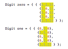
Each digit takes up a 3x5 grid of pixels. These 3x5 grids are defined in Digit.h. This function loops through each pixel in a digit and assigns it to it’s corresponding pixel in the leds grid.
void showDigitLEDs(int digit, int startColumn) { // Get a 3x5 mapping of which pixels to display for this digit Digit d = digits[digit]; // Loop through this 3x5 array pixels and set the LEDs for (int x = 0; x < DIGIT_WIDTH; x++) { for (int y = 0; y < DIGIT_HEIGHT; y++) { // The pixels array tells us to show this LED or set it to Black if (d.showPixel(x, y)) { leds(startColumn + x, y) = getColor(startColumn + x); } else { leds(startColumn + x, y) = CRGB::Black; } } }}
Each digit is a two-dimensional array of 0s and 1s. This screenshot shows the 1s highlighted. We can loop through these 2d arrays of “pixels” and check if the corresponding LED should be lit.
We store this 2d array of pixels in the Digit struct.
struct Digit { bool pixels[DIGIT_HEIGHT][DIGIT_WIDTH]; bool showPixel(int x, int y) { return pixels[DIGIT_HEIGHT - y - 1][x]; }};
The function showPixel returns whether a pixel in the 3x5 digit grid should be lit. It swaps the (x, y) syntax to [y][x] because the pixel arrays are organized row-then-column. It also flips the y value because the pixels are stored top-to-bottom, and the clock pixels are rendered bottom-to-top.
Then we take all the Digit objects 0-9 and make a global array digits.
First, use the map() function to convert the column to a hue. The Arduino map() function is a handy Arduino built-in function that lets you convert a value from a starting range to a destination range. Here, we’re mapping the column from it’s range 0-WIDTH (which is 16) to the range of a hue 0-255. For example, when column is 2, hue becomes 32.
Then we pass the hue to a FastLED function CHSV() to create an HSV color (CHSV documentation). In the FastLED library, hue, saturation, and value are all values between 0-255 but a typical HSV color has different ranges. Hue is usually a value 0-360 (as in 360 degrees on a color wheel), and saturation and value are usually a percentage 0-100. Here we set the saturation to it’s max of 255 and brightness to the global BRIGHTNESS variable we defined at the very beginning of the rainbow clock program.
If the colon is flashed on, set those 2 LEDs to white. In the main file, we defined the COLON_COLUMN to be column 8. This function sets the pixels in that column on rows 1 and 3.
void showColonLEDs() { // If the colon is flashed on, set the 2 LEDs to white in the middle column, // rows 1 and 3 if (c.isColonVisible()) { CHSV white = CHSV(0, 0, BRIGHTNESS); leds(COLON_COLUMN, 1) = white; leds(COLON_COLUMN, 3) = white; }}
This class lets us reference the LEDs conveniently with syntax like leds(x, y) = color. The main part of the code is the function xyCoordsToIndex which converts x, y coordinates to an index on the one-dimensional array that snakes back and forth on the grid, which is how FastLED stores LED data.
The LEDGrid object is defined like this in the main rainbow-clock.ino file:
Define private variables. These cannot be accessed outside of this class.
class LEDGrid {private: int _width; // number of pixels across int _height; // number of pixels high int _startPixel = BOTTOM_LEFT; // the first pixel on the subgrid, either // BOTTOM_LEFT or TOP_LEFT CRGB *_leds; // pointer to the LED array
The FastLED leds array is usually defined with this syntax: CRGB leds[NUM_LEDS]. That syntax will allocate the amount of memory needed for the array. It requires NUM_LEDS to be a static variable so it knows how much memory to allocate. But since this class is flexible enough to accept different grid dimensions, we want our _leds size to be _width * _height, which are both dynamic variables whose values aren’t known at first. Instead, we can define a pointer with the syntax *_leds, which doesn’t allocate any memory, but instead points to memory. Then we allocate the memory later when we know the value of _width and _height. This happens in the constructor, using the new operator (see next section).
The public variables in this class are BOTTOM_LEFT and TOP_LEFT, which are the two different positions of the starting pixel on the grid.
public:
  static constexpr int BOTTOM_LEFT = 0;
  static constexpr int TOP_LEFT = 1;
The [] operator lets us reference the LEDGrid object with the syntax leds[i]. This is used in the setup() function where FastLED.addLEDs is called, where we tell FastLED our LED array variable.
The () operator lets us reference the LEDGrid object with the syntax leds(x, y). It coverts the x and y values to the corresponding index on the one-dimensional FastLED _leds array.
struct CRGB &operator()(int x, int y) { return _leds[_xyCoordsToIndex(x, y)];}
The LEDs are wired as one long strand that snakes back and forth. In order to reference this strand with x, y coordinates, we need to calculate the index. The equation varies slightly depending on the row and the start pixel.
The core equation to convert x, y to one long strand is y * width + x. But, we need to flip the x horizontally for odd rows because the strand snakes back and forth. And also, if the starting pixel is at the top, we need to flip all the y values vertically.
int _xyCoordsToIndex(int x, int y) { // For odd rows, flip the x value horizontally if (y % 2 == 1) { x = _flipHorizontal(x); } // If the start pixel is at the top, flip the y value vertically if (_startPixel == TOP_LEFT) { y = _flipVertical(y); } return y * _width + x;}// Given a column, returns the opposite column horizontallyint _flipHorizontal(int x) { return _width - x - 1; }// Given a row, returns the opposite row verticallyint _flipVertical(int y) { return _height - y - 1; }
This page will walk through all the parts of the code that have to do with reading and handling the button state. The rest of the code related to the clock and LED functionality will be skipped on this page but covered on the other pages in this section.
Include the Button.h class file in this repository.
#include "Button.h"
Note:.ino files don’t need to be included. All .ino files are automatically concatenated together into one big file when you compile.
Define the pin number the button is soldered to on the ESP32.
// Button variables#define BUTTON_PIN 15 // pin D15 on the ESP32
Create an instance of the button class named button, tell it the pin number we defined.
Button button(BUTTON_PIN);
The setupButton function configures the specified pin to behave as an input.
void setup() { // Tell the button object which pin to read from button.setupButton(); // ...}
On every iteration of the loop, the handleButtonState function reads the current state of the button and checks if a click or a long press has occurred, and if one has, it handles it by calling the necessary functions in the clock code. The code within the function is explained further below.
void loop() { // ... // Read the button state from the pin and check for a click or a long press handleButtonState(); // ...}
Here’s the whole function. We’ll go through each piece one at a time next.
void handleButtonState() { // Read the value from the data pin button.update(); if (button.longPressed) { // Go to next mode when button is long pressed c.mode = (c.mode + 1) % NUM_MODES; } if (button.clicked) { // Increment the digit according to which mode we're in if (c.mode == EDIT_HOUR) { c.hour++; c.hour %= 24; } else if (c.mode == EDIT_MINUTE_DIGIT_1) { c.minute += 10; c.minute %= 60; } else if (c.mode == EDIT_MINUTE_DIGIT_2) { c.minute++; if (c.minute % 10 == 0) { // If the minute wraps from 9 -> 10, it increments the left minute // digit, which was already set in the last edit mode, so subtract 10 to // keep the left minute digit the same c.minute -= 10; } c.minute %= 60; } // Tell the clock object that this is the new time if (c.mode != SHOW_TIME) { c.setNewTime(c.hour, c.minute); } }}
On the first line, update is called, (a function defined on the Button class, and is explained further below) which reads the state of the button from the pin on the ESP32 and determines if a click or a long press occurred.
If a long press occurred, we go to the next mode. Long pressing over and over will continuously cycle through all 4 modes: SHOW_TIME, EDIT_HOUR, EDIT_MINUTE_DIGIT_1, EDIT_MINUTE_DIGIT_2. % NUM_MODES is used to wrap back to 0 every time we reach the last mode. 0 -> 1 -> 2 -> 3 -> 0 -> etc
if (button.longPressed) { // Go to next mode when button is long pressed c.mode = (c.mode + 1) % NUM_MODES;}
If a click occurred, figure out which edit mode we’re in. (If we’re not in edit mode, it will run through all this code without anything happening.) In each if block, edit the digit: hour digit, left minute digit, etc. Then, in any edit mode, set that new time with c.setNewTime.
if (button.clicked) { if (c.mode == EDIT_HOUR) { // ... } else if (c.mode == EDIT_MINUTE_DIGIT_1) { // ... } else if (c.mode == EDIT_MINUTE_DIGIT_2) { // ... } if (c.mode != SHOW_TIME) { c.setNewTime(c.hour, c.minute); }}
Jumping in to what happens within one of the if blocks, increment the hour digit, then use %= 24 to wrap back to 0 every time 24 is reached (24 % 24 = 0).
if (c.mode == EDIT_HOUR) { c.hour++; c.hour %= 24;} ...
The right-hand-side minute digit has one extra step because when that right digit wraps from 9 -> 0, the minute value increments from 9 -> 10, which will also increase the left minute digit by 1. But we already set the left minute in the previous edit mode, so we want to keep it the same as it was. So we handle this special case by subtracting 10 every time the digit wraps from 9 -> 0, ie. every time the new incremented value is divisible by 10 (% 10).
Example Timer usage: (this is not rainbow clock code)
Timer myTimer = {10000}; // Set up a timer to last 10 seconds (10000 milliseconds)myTimer.reset(); // Start the timerif (myTimer.complete()) { // ... Do something here ... myTimer.reset(); // Start the timer again (if you want)}
The timer we’ll use to time a long press is set up as the private variable _longPressTimer on the button class. Other private variables include pin number, the previous button state, and a flag to indicate if a long press was triggered.
class Button {private: int _pin; // Data pin on the ESP32 int _prevState = BUTTON_UP; // The state of the button in the last loop bool _longPressTriggered = false; // Prevents a click from triggering when // lifting the button up after a long press Timer _longPressTimer = {LONG_PRESS_DURATION}; // For timing a long press
Public variables include the two button states LOW and HIGH which represent voltages. In this case, the button reads as LOW when it’s held down, and HIGH when it’s not held. clicked and longPressed are the two button statuses to be referenced outside this class to check if the button was just clicked or long pressed.
public:
  static constexpr int BUTTON_DOWN = LOW;
  static constexpr int BUTTON_UP = HIGH;

  bool clicked = false;     // Sets to true when button is clicked
  bool longPressed = false; // Sets to true when button is lock pressed
When the button is constructed, the pin number on the ESP32 is passed in. The setupButton is called from the main setup() function to orient the pin as an input pin.
The purpose of the update() function is to set the public variables clicked and longPressed so that somewhere else in code can reference them, eg. with if (button.clicked) {, and cause things to happen after button interactions.
The first thing that happens is we read the signal from the pin. This sets the state to whether the button is up or down right now.
void update() {
  int state = digitalRead(_pin); // Read the signal from the pin
Reset the click and long press status to false. If a click or a long press happened in the previous iteration of the loop, then one of these will be true. Reset them to false so we don’t trigger another click or long press.
  // Reset the click and long press status
  clicked = false;
  longPressed = false;
There are three button conditions being checked for:
The button is down and was previously up: Could be a click or a long press. We won’t know until the button is released. Start the timer.
  if (state == BUTTON_DOWN && _prevState == BUTTON_UP) {
    _longPressTimer.reset();
The button is down and it’s been down for 2 seconds: Trigger a long press. Also start the timer over. Also set the _longPressTriggered flag to true until the button is lifted. This flag prevents a click from triggering when the user releases the button from this long press.
  } else if (state == BUTTON_DOWN && _longPressTimer.complete()) {
    longPressed = true;
    _longPressTimer.reset();
    _longPressTriggered = true; // Set this to true until button is lifted
The button is up and was previously down: Trigger a click. Unless its the user releasing the button after just long pressing. In that case, don’t trigger a click. Check if it was a long press by checking _longPressTriggered, and if so, reset it back to false to indicate the long press is complete. If it wasn’t a long press, proceed with triggering a click.
The Arduino IDE comes with loads of well explained examples. In the Arduino IDE go to File -> Examples. Most libraries you install like FastLED also include examples that show up in the same File -> Examples menu after you install the library.
Random Nerd Tutorials is full of guides on ESP32, Arduino, Raspberry Pi, and coding. Their guides are extremely well written, clear, and thorough. They were a big inspiration for me to want to write guides.
There are tons of articles, forum posts, and videos out there about Arduino code and ESP32s. If you’re running into a code problem try searching for the problem or error you’re getting with the word “Arduino”. (Even though we’re uploading code to an ESP32, we’re still writing in the “Arduino” programming language.)
Check that you have the ESP32 board selected in the Tools -> Port menu. If it is not showing up in the menu, see the next section.
ESP32 not showing up in Port menu in Arduino IDE §
Try cycling power: Unplug and replug USB cable.
Try a different USB cable. The cable that came with your clock should work, but strange things happen. Make sure the cable is not power-only and is data sync capable.
The LEDs might be using too much power. Try disconnecting the LEDs from the board by opening the clock and disconnecting the plastic LED connector. Then unplug the USB from your computer and plug it back in. If this fixes it you might have uploaded code that was resulting in the LEDs using too much power, for example turning all the LEDs on white at full brightness. Try uploading new code that uses less power (eg. lower brightness, fewer LEDs on, or a lower power-consuming color like Red)
If you are using the clock code in this repository, you might need to change the START_PIXEL variable from LEDGrid::TOP_LEFT to LEDGrid::BOTTOM_LEFT or vice versa. See LED grid layout for more details.
You may need to open the clock and physically rotate the LED Grid. The start pixel should be on the top left or bottom left of the clock as you are looking at the front of the grid.
Arduino is its own programming language based on C and C++. The Arduino language has its own built-in functions that are specific to hardware coding like delay(), pinMode() (see a full list of built-in functions) and Arduino programs must follow a specific code structure with two functions: setup() (which runs once at the beginning) and loop() (which runs over and over forever). For more details about the code structure visit this page: Basic code and file structure