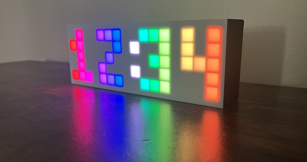
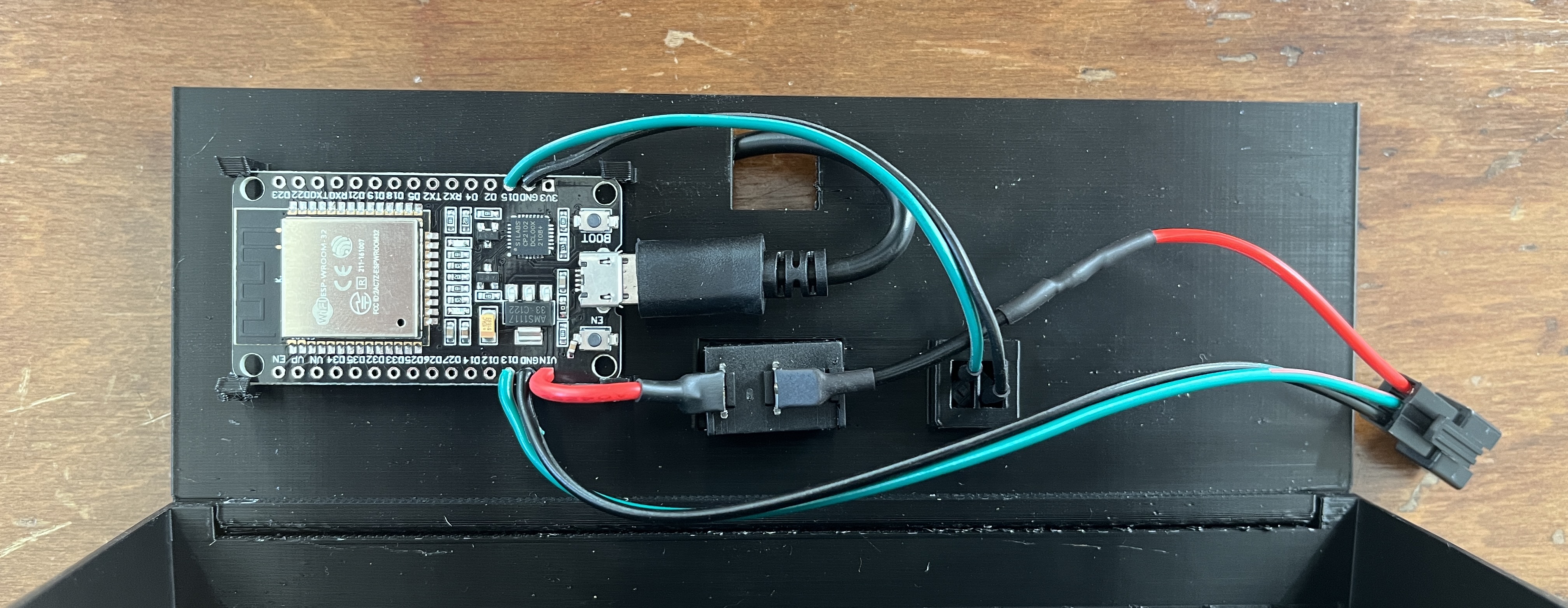
The clock itself is 3D printed, has an on/off switch on the back, and also has a button on the back for manually setting the time. The back panel of the clock hinges open to reveal a programmable ESP32 microcontroller and a 5x16 grid of LEDs. A data-sync capable microUSB cable is included.
Materials
- 3D printed hingebox (black) and screen (white)
- ESP32
- LED Matrix
- On/off switch
- Button
- Data sync micro USB cable
Wiring Diagram
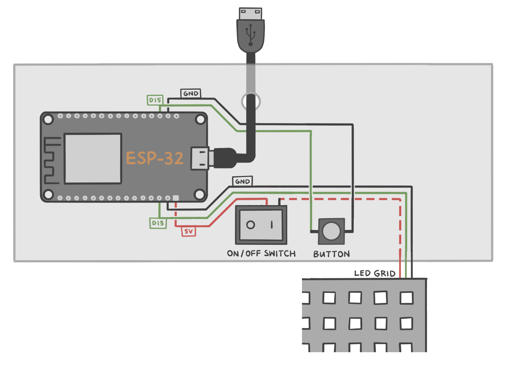
| ESP32 | Button | LED Grid |
|---|---|---|
| Vin | Power (via on/off switch) | |
| GND | GND | |
| GND | pin 1 | |
| D13 | Data | |
| D15 | pin 2 |
NOTE
The on/off switch only turns off power to the LEDs, not the whole system. So if you turn the switch off and leave the USB cable plugged in, the ESP32 board will still be powered, and it will still keep accurate time.