Sub-grid variations
There are two different hardware configurations your clock could have. These two variations are accounted for in the code. This page explains these variations.
The 5x16 grid in the clock was originally a 16x16 pixel matrix that was cut into three 5x16 pixel sub-grids. Because the wiring embedded in these grids runs back and forth in a snake pattern, one of these three sub-grids has a different starting pixel position, and the arrangement of LEDs is flipped.
| Original 16x16 Grid | LED Arrangement Diagram |
|---|---|
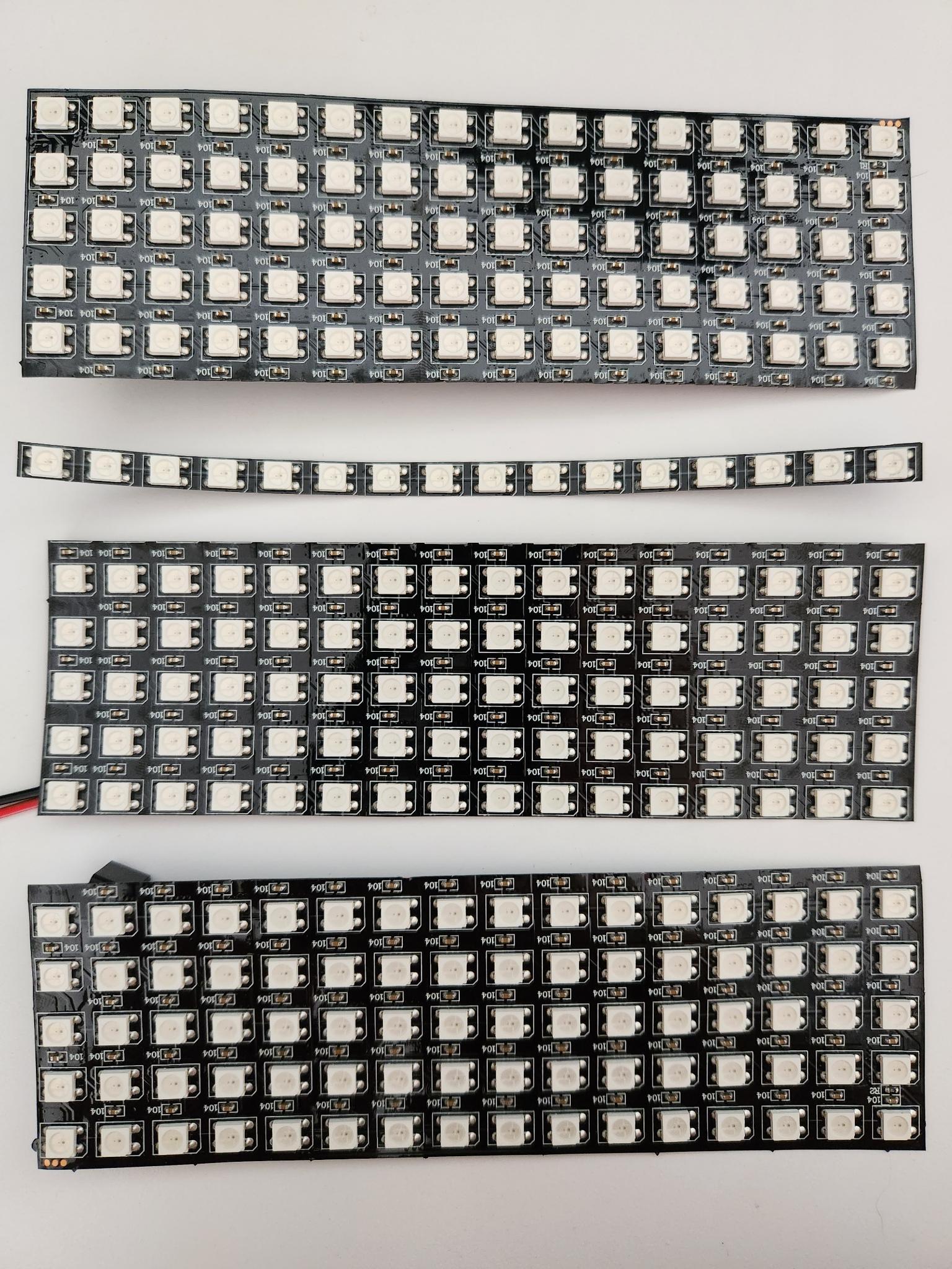 | 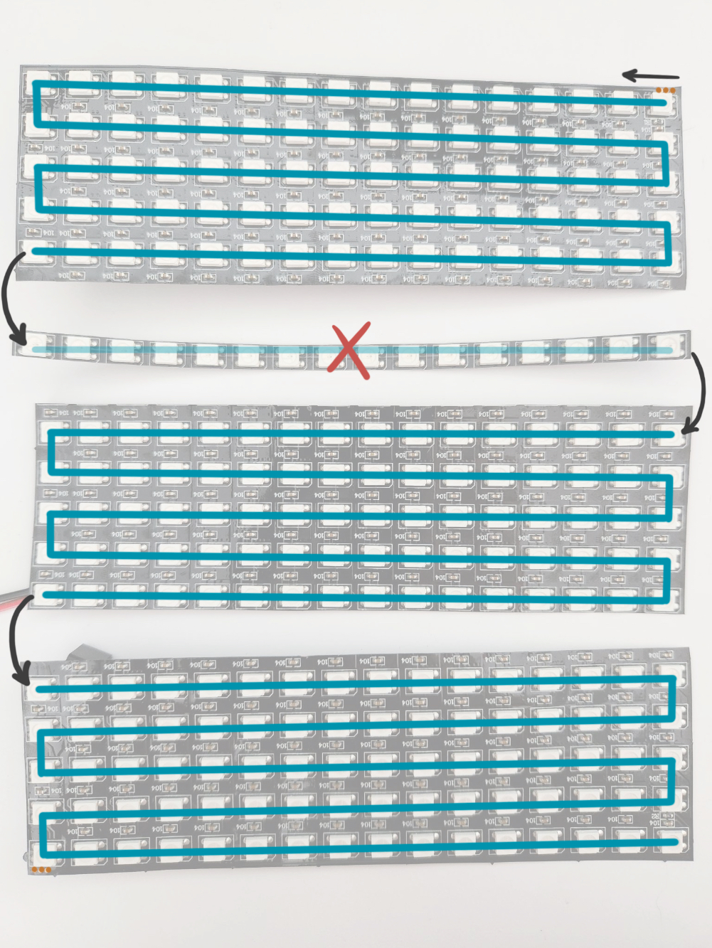 |
Which sub-grid variation do you have?
Your grid’s starting pixel should be on either the bottom left or the top left (looking at the front of the clock). You can hinge open the back panel of your clock to access your sub-grid. Then you can compare yours to the photos below to figure out which starting pixel you have.
If for some reason your starting pixel is on the right, rotate your grid 180 degrees so that it is on the left. The code only accounts for starting pixels on the bottom left or top left.
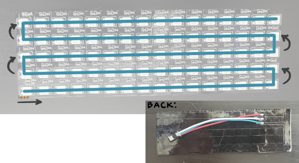
Sub-grids with BOTTOM_LEFT start pixel
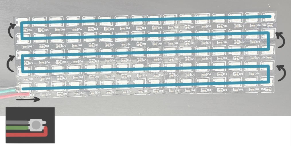
Some grids have the wires soldered directly to the flat part on the back (see photo below). These have the BOTTOM_LEFT start pixel.
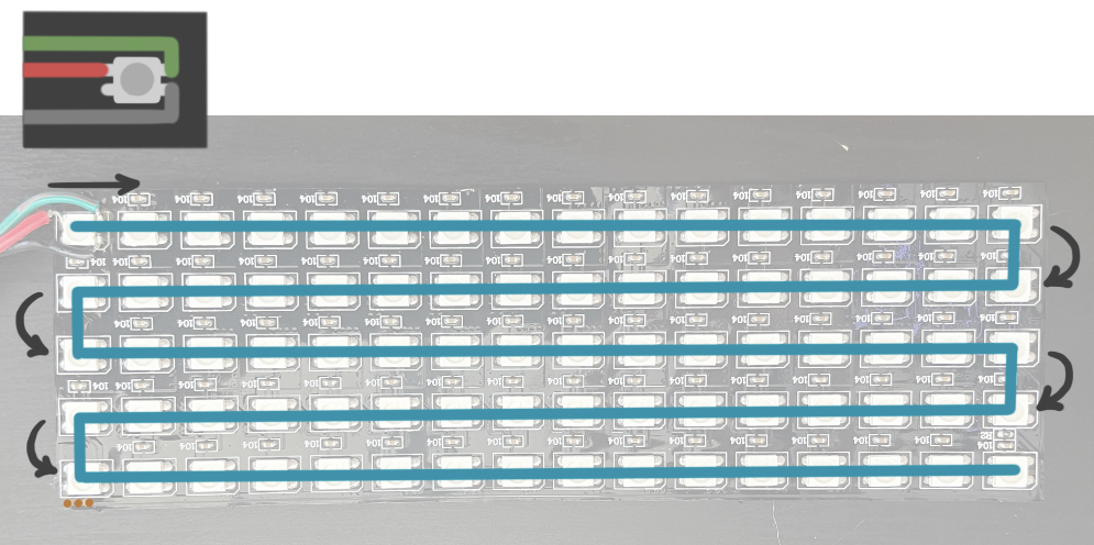
Sub-grids with TOP_LEFT start pixel
Set your starting pixel in the code
In the main file rainbow-clock.ino, there is a variable START_PIXEL. Change this variable to be set to LEDGrid::BOTTOM_LEFT or LEDGrid::TOP_LEFT according to your sub-grid’s start pixel.
#define START_PIXEL LEDGrid::BOTTOM_LEFT  // or LEDGrid::TOP_LEFT

LEDGrid leds(WIDTH, HEIGHT, START_PIXEL);